How To Wire Light Switches
First, ensure you’re always wearing the proper safety equipment while working. You should have on rubber electrical gloves and rubber-soled shoes at all times. Rubber is an insulator, which means that if electricity does happen to jump out at you, it won’t be able to pass through your rubber safety equipment. Water and other liquids, on the other hand, are conductors and should be kept safely away from your work area.
Second, before beginning any electrical work, it’s essential to turn off the power at the circuit breaker box. If you’re unsure which breaker leads to the light switch you’re working on, test each breaker by turning the switches on and off until you find the match. It is a good idea to test the wires using a circuit tester to verify the power is off.
Remove the switch plate.
Identify and Disconnect the Wires. Before you disconnect the wires, it’s helpful to identify the electrical wires by their color codes. Here are the main points to know about the colors of wires when you’re wiring a light switch:
- Black wire: The black wire (sometimes red) is the load or hot wire that carries the voltage through the switch. In a light switch, the black wires connect to the brass screws on the side of the switch, which are known as terminal screws.
- White wire: The white wire is the neutral wire, and it’s sometimes connected to another white wire covered by a wire nut.
- Copper wire: The bare copper wire is considered the ground wire. It can also be green or green with a yellow stripe. In the switch, the ground wire is attached to the green grounding screw.
Inspect and Prepare the Wires. Check over the ends of the wires for fraying or shredding. If you locate any issues, trim away the damaged ends using wire cutters or a multi-tool. This is an important step, as you want to ensure that any part of the wire that’s touching the screws is in good condition. Using a pair of wire strippers, remove half an inch of wire insulation, leaving that much wire exposed. Then, bend the exposed wire into a “U” shape so that it can be positioned around the screw in a clockwise direction.
Wire the Switch (see below), then Attach the Light Switch, Test the Switch and Attach the Cover Plate
Wiring a single-pole switch incorrectly typically results in the light not turning on. Single-pole light switches only have an “on” and “off” function, so it's only essential that the hot wire connects to one terminal and the wire to the light connects to the other. Examples of incorrect wiring on a single-pole switch include not sufficiently tightening the terminal connections or ground wire. These instances can cause arcing and trip a breaker or create a fire hazard.
How To Wire a 2-Way Light Switch
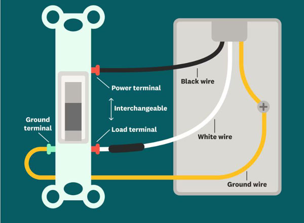
Start by wrapping the exposed portions of the black wire and white wire around the brass terminal screws on the right side of the switch in a clockwise motion. It doesn’t matter which one goes on the top screw and which one goes on the bottom. With your screwdriver, tighten the screws in a clockwise direction to secure the wires into place.
Repeat this process with the copper or green wire, attaching it to the copper or green screw on the lower left side, also called the ground terminal. If you’re installing a double or three-way light switch, make sure to wire to each terminal.
(Typically, the black or red wire goes to the brass-colored screw (hot), the white wire to the silver-colored screw (neutral) and the green or bare wire to the green screw (ground).)
How To Wire a 3-Way Light Switch
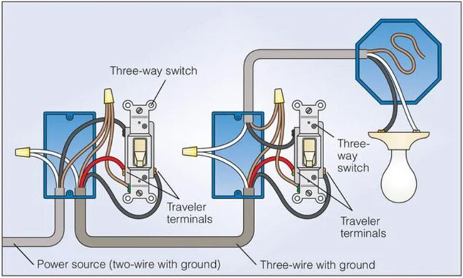
Unlike single-pole switches, which control lights from one location, 3-ways work in pairs. You must have two of them — and only two. (For more than two locations, add 4-way switches.) Note; only one of the switches can be a dimmer switch, otherwise the lights just flicker.
Below, I’ll show you the most common way to wire a 3-way switch. It’s what most electricians use today, because it’s easy and saves money.
Here’s how it works: Power comes into the first switch from the power source. Two wires called “travelers” connect the first switch to the second one. Then power leaves the second switch to go to the light. No matter which switch you flip, the light responds.
Wire the first switch (one closest to the breaker box)
Cut a few 6-in. lengths of bare copper wire to use as grounding pigtails. Note: A pigtail wire is a short length of wire that connects at one end to a screw terminal on an electrical device, with the other end joined to circuit wires with a wire connector (wire nut).
Splice the two bare grounds (copper wires) from the cables to a 6-in. copper pigtail. Make a hook in the end of the pigtail using a needle nose pliers or a bending hole on a wire stripper and wrap clockwise around the green screw, which is the ground screw. Tighten.
Splice the two neutrals (white wires) together. Do not attach them to the switch.
Secure the black wire from the 14-2 power supply cable to the black (common) screw on the 3-way. (Make a hook like before.)
Secure the traveler wires (black and red) from the 14-3 cable that goes to the 2nd light switch to the brass screws. It doesn’t matter which one goes where. Wrap electrical tape around the switch to cover the exposed terminals and secure the switch into the box.
Wire the second switch
Splice the two bare grounds to a 6-in. copper pigtail and attach the pigtail to the green screw.
Splice the two neutrals together. Do not attach to the switch.
Secure the black wire from the 14-2 cable going to the light to the black (common) screw.
Secure the black and red traveler wires from the 14-3 cable to either of the brass traveler screws. (Again, it doesn’t matter which.) Wrap the switch with tape and attach it to the box.
Finish
Check that switches are secure to the boxes and add faceplates. Turn on the breaker. Test your lights by flipping on and off at each location. If something’s not working, turn off the breaker before checking it out! Double-check that you have travelers on the brass screws and power on the black/common.